


Electric power transmission is the bulk transfer of electrical power (or more correctly energy), a process in the delivery of electricity to consumers. A power transmission network typically connects power plants to multiple substations near a populated area. The wiring from substations to customers is referred to as Electricity distribution, following the historic business model separating the wholesale electricity transmission business from distributors who deliver the electricity to the homes. Electric power transmission allows distant energy sources (such as hydroelectric power plants) to be connected to consumers in population centers, and may allow exploitation of low-
Usually transmission lines use three phase AC current. Single phase AC current is sometimes used in a railway electrification system. High-
Electricity is transmitted at high voltages (110 kV or above) to reduce the energy lost in transmission. Power is usually transmitted as alternating current through overhead power lines. Underground power transmission is used only in densely populated areas because of its higher cost of installation and maintenance when compared with overhead wires, and the difficulty of voltage control on long cables.
A power transmission network is referred to as a "grid". Multiple redundant lines between points on the network are provided so that power can be routed from any power plant to any load center, through a variety of routes, based on the economics of the transmission path and the cost of power. Much analysis is done by transmission companies to determine the maximum reliable capacity of each line, which, due to system stability considerations, may be less than the physical or thermal limit of the line. Deregulation of electricity companies in many countries has led to renewed interest in reliable economic design of transmission networks. However, in some places the gaming of a deregulated energy system has led to disaster, such as that which occurred during the California electricity crisis of 2000 and 2001.
Overhead transmission
Overhead conductors are not covered by insulation. The conductor material is nearly always an aluminum alloy, made into several strands and possibly reinforced with steel strands. Copper was sometimes used for overhead transmission but aluminum is lower in weight for equivalent performance, and much lower in cost. Overhead conductors are a commodity supplied by several companies worldwide. Improved conductor material and shapes are regularly used to allow increased capacity and modernize transmission circuits. Conductor sizes range from #6 American wire gauge (about 12 square millimeters) to 1,590,000 circular mils area (about 750 square millimeters), with varying resistance and current-
Today, transmission-
Since overhead transmission lines are un-
.
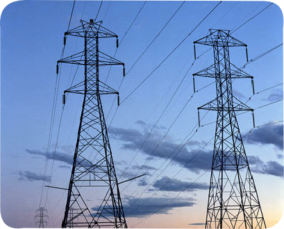
High voltage overhead power lines.
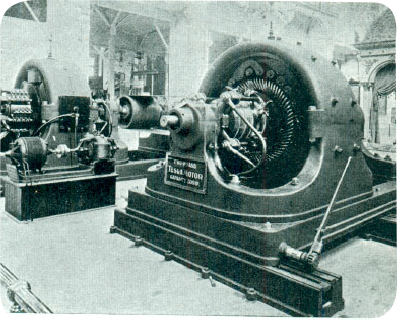
Nikola Tesla's Alternating current polyphase generators on display at the 1893 World's Fair in Chicago. Tesla's polyphase innovations revolutionized transmission.
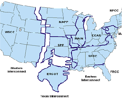
American Electric Grid
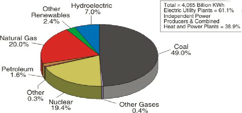
Total breakdown of electrical producing systems in the United States.
Underground transmission
Electric power can also be transmitted by underground power cables instead of overhead power lines. They can assist the transmission of power across:
Densely populated urban areas
Areas where land is unavailable or planning consent is difficult
Rivers and other natural obstacles
Land with outstanding natural or environmental heritage
Areas of significant or prestigious infrastructural development
Land whose value must be maintained for future urban expansion and rural development
Some other advantages of underground power cables:
Less subject to damage from severe weather conditions (mainly wind and freezing)
Greatly reduced emission, into the surrounding area, of electromagnetic fields (EMF). All electric currents generate EMF, but the shielding provided by the earth surrounding underground cables restricts their range and power.
Underground cables need a narrower surrounding strip of about 1-
Some disadvantages of underground power cables:
Under grounding is more expensive, since the cost of burying cables at transmission voltages is several times greater than overhead power lines, and the life-
Whereas finding and repairing overhead wire breaks can be accomplished in hours, underground repairs can take days or weeks, and for this reason redundant lines are run.
Operations are more difficult since the high reactive power of underground cables produces large charging currents and so makes voltage control more difficult.
The advantages can in some cases outweigh the disadvantages of the higher investment cost, and more expensive maintenance and management.
Most high-
History
In the early days of commercial use of electric power, transmission of electric power at the same voltage as used by lighting and mechanical loads restricted the distance between generating plant and consumers. In 1882 generation was with direct current, which could not easily be increased in voltage for long-
Due to this specialization of lines and because transmission was so inefficient that generators needed to be close by their loads, it seemed at the time that the industry would develop into what is now known as a distributed generation system with large numbers of small generators located nearby their loads.
In 1886 in Great Barrington, Massachusetts, a 1kV AC distribution system was installed. That same year, AC power at 2kV, transmitted 30km, was installed at Cerchi, Italy. At an AIEE meeting on May 16, 1888, Nikola Tesla delivered a lecture entitled A New System of Alternating Current Motors and Transformers, describing the equipment which allowed efficient generation and use of polyphase alternating currents. The transformer, and Tesla's polyphase and single-
Regarded as one of the most influential innovations for the use of electricity, the "universal system" used transformers to step-
By allowing multiple generating plants to be interconnected over a wide area, electricity production cost was reduced. The most efficient available plants could be used to supply the varying loads during the day. Reliability was improved and capital investment cost was reduced, since stand-
The first transmission of three-
Voltages used for electric power transmission increased throughout the 20th century. By 1914 fifty-
The rapid industrialization in the 20th century made electrical transmission lines and grids a critical part of the economic infrastructure in most industrialized nations. Interconnection of local generation plants and small distribution networks was greatly spurred by the requirements of World War I, where large electrical generating plants were built by governments to provide power to munitions factories; later these plants were connected to supply civil load through long-
High-voltage direct current
High voltage direct current (HVDC) is used to transmit large amounts of power over long distances or for interconnections between asynchronous grids. When electrical energy is required to be transmitted over very long distances, it is more economical to transmit using direct current instead of alternating current. For a long transmission line, the lower losses and reduced construction cost of a DC line can offset the additional cost of converter stations at each end. Also, at high AC voltages, significant (although economically acceptable) amounts of energy are lost due to corona discharge, the capacitance between phases or, in the case of buried cables, between phases and the soil or water in which the cable is buried.
HVDC links are sometimes used to stabilize against control problems with the AC electricity flow. In other words, to transmit AC power as AC when needed in either direction between Seattle and Boston would require the (highly challenging) continuous real-
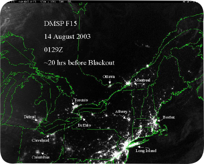
Eastern sea board of the United States prior to the Blackout.
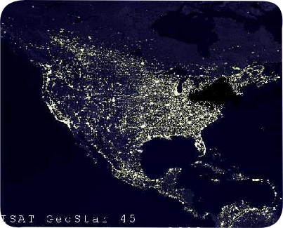
The United States after the Blackout on the Eastern sea board. Notice the dark spot between the United States and Canada.
